TM 9--2520--215--34
0076 00--5
OUTPUT PRESSURE AND BRAKE COOLANT PUMP ASSEMBLY REPAIR –
CONTINUED
0076 00
ASSEMBLY
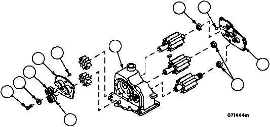
1. Install replacement needle bearings (8 and 11) into body (17) or cover (5) and (14) if removed, by placing driver
against numbered ends of bearing races. Drive bearings 0.090 inch below inside machined surfaces in pump
body and brake coolant pump cover (14). Bearing must be seated against shoulder in output pressure oil pump
cover (5). Install bolt (6) and flat washer (7) in output pressure pump cover. Dowel pins (18) and (19) must
protrude ¼ inch when installed in covers.
5
7
6
8
8
11
11
19
17
14
18
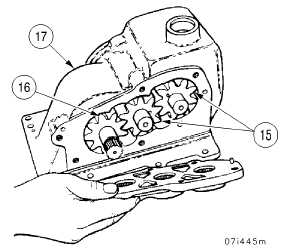
2. Install internal drive gear (16), short end first, into pump body (17). Install two idler gears (15), long ends first in
pump body (17).