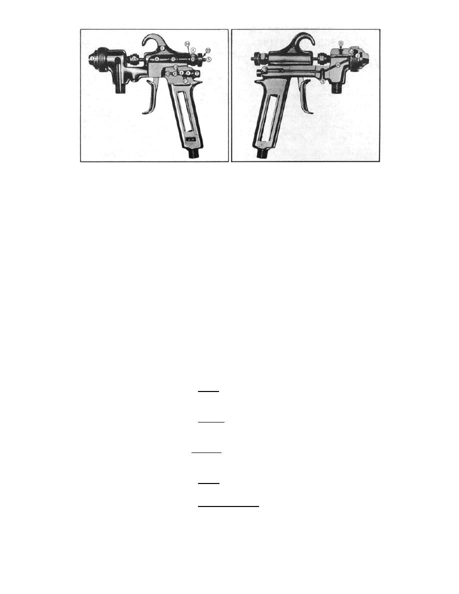
1.
nozzle
7.
air valve spring retainer
13.
fan adjustment
19.
small fluid spring
2.
fluid tip
8.
air valve spring
14.
nozzle adapter
20.
fluid spring washer
3.
trigger screw
9.
air valve
15.
nozzle adapter lock screw
21.
fluid spring
4.
fluid tension adjustment
10.
air valve pin
16.
air line passages
22.
fluid adjustment knurled nut
5.
plunger adjusting rod
11.
clean out plug(s)
17.
air inlet passage
bushing
6.
plunger
12.
air line screws
18.
packing gland
23. air valve pin bushing
drills are available, a piece of
8. Pitted or distorted air valve.
DISASSEMBLY
tempered wire will help. (Soft wire will
9. All worn or tired springs -
(MOST
GUNS)
break and clog hole.) Don't miss the
they'll break when you need them if
two air lines leading into the nozzle
you don't.
A small box to hold the parts is
adapter. They are more likely to clog
recommended.
than the rest.
RE-ASSEMBLY
1. Submerge gun in good strong
2. A good soaking in thinner will
solvent (not lye or corrosive acid) until
loosen most of the paint residue in the
Follow the some general order
all exterior paint and dirt can be easily
fluid passage. This is easily done by
as in disassembly, but in reverse.
removed.
supporting the gun upside down and
1. Grease all springs well with
2. Take off nozzle and fluid tip,
filling the fluid hose connection with
heavy cup grease.
and place in solvent.
solvent. The hole behind the fluid
2. When installing plunger be
3. Unscrew the trigger screw
hose connection ought to look
sure slot is in line with trigger so that
which goes through the hook and pull
moderately clean inside.
the trigger may slide through.
out the trigger.
3. The parts should be free from
Adjustment screw may be left in
4. Unscrew the fluid tension
paint, rust and dirt. A wire wheel is the
plunger after insertion.
adjustment completely.
easiest for cleaning them, but steel
3. Be sure fluid spring tension
5. Take the plunger adjusting
wool or very fine emery cloth will do in
assembly goes back together right.
rod out of the tension adjustment
the field.
From back to front:
assembly. Reinsert it into the plunger
fluid tension adjustment assembly,
and twist until it engages the plunger.
PARTS REPLACEMENT
small spring, brass washer, large
6. Pull out the plunger with the
spring.
adjusting rod.
4. If the fluid adjustment knurled
1. Nozzle-if slot has begun to
7. Unscrew air valve spring
nut doesn't turn the adjustment screw,
wear into a round hole in the center.
retainer and remove air valve spring,
it is often possible to re-engage the
Fan pattern will soon begin to distort if
air valve and air valve pin.
nut by placing a large pointed center
you don't.
8. Remove clean-out plugs, air
punch on the bushing at the back and
2. Fluid tip-with deep chamfer at
line screws, and fan adjustment if
hitting it with a hammer.
the back or a distorted front neck. It's
there is one.
5. Oil plunger at packing gland
a good idea always to replace tips
Neither the nozzle adapter nor
and where it passes into casting.
when overhauling.
the lock screw at the top of the head
6. New packing should be used
3. Plunger-with deep groove
should be touched except at the
and the packing nut tightened until the
around conical point.
factory.
plunger will no longer return to its
4. Always repack the packing
foremost seated position when the
gland with preformed packing.
CLEANING
trigger is pulled. Then back off the nut
5. Trigger- if badly pitted on the
a turn or two until the plunger slides
back of the shank where it engages
1.
Clean out all air passages
freely.
the air valve pin.
in the gun with a twist drill held in the
7. Oil air valve pin through
6. Plunger adjustment screw if
hand (1/8" on GAT and 5/32" on G-6).
trigger slot.
bent or threads are worn.
The main air inlet may also be cleaned
7. Bent air valve pin.
with
a
1/4"
drill.
If
no
2


