TB 43-0213
D-13. Torque Values.
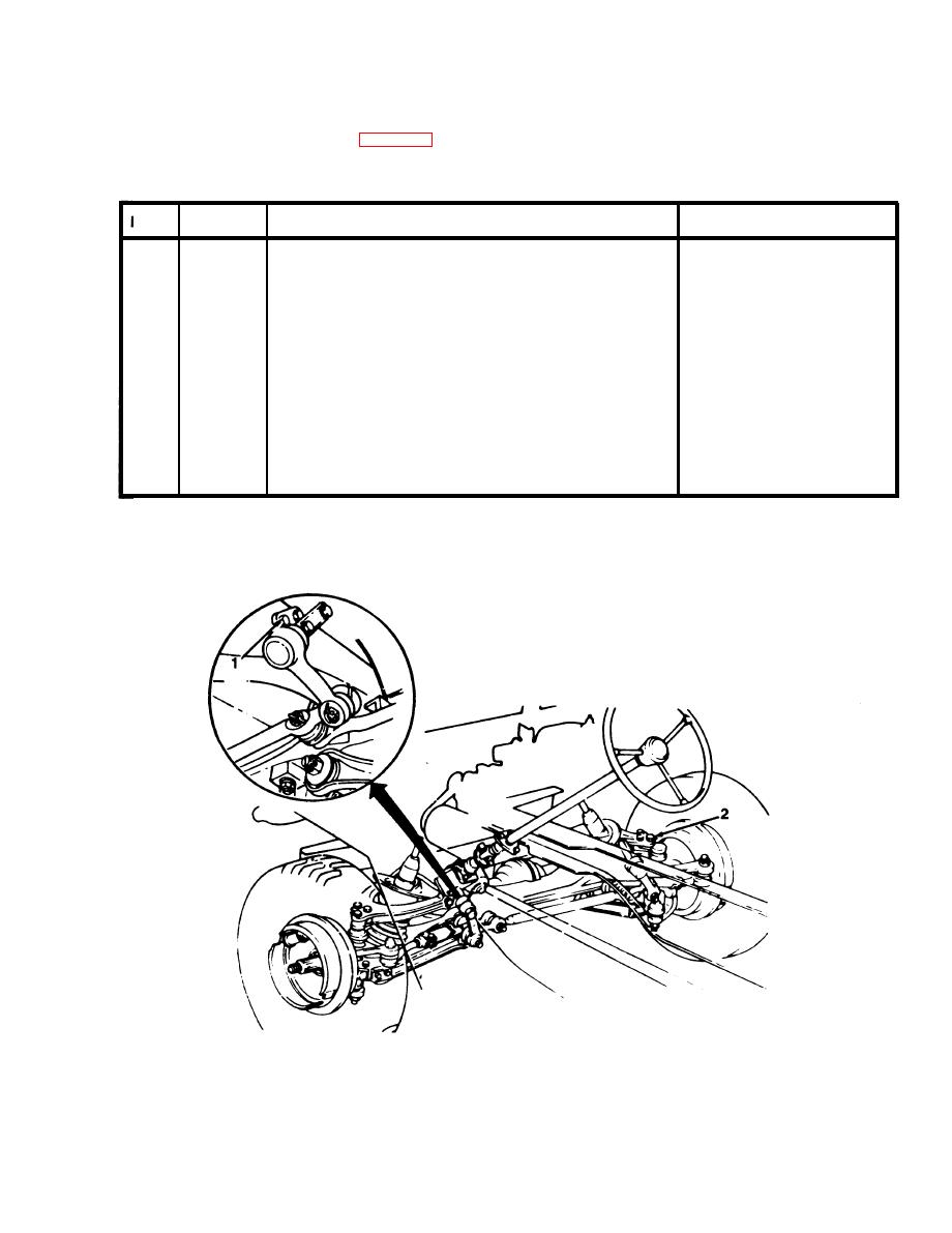
a. Body attaching parts listed in Table D-3 are to be tightened to the torque values given. Refer to Figure D-15
through Figure D-18 for the location of these parts and assemblies.
Table D-3. Specific Torque Values.
Figure
Number
Items
Torque
Idler arm bracket to frame bolts.
D-15
1
25-30 Ib.-ft. (34-41 Nm)
Front suspension ball joint mounting bolts.
D-15
2
35-45 Ib.-ft. (47-61 Nm)
D-16
Rear suspension bracket to body bolts.
3
40-55 Ib.-ft. (54-75 Nm)
D-16
4
Front and rear propeller shaft bolts.
15-20 Ib.-ft. (20-27 Nm)
D-16
5
Rear suspension arm pivot bolts.
65-70 Ib.-ft. (88-95 Nm)
D-17
Front suspension upper control arm mounting bolts.
70-90 lb.-ft. (95-122 N-m)
6
D-17
7
Front suspension crossmember bolt.
27-37 Ib.-ft. (37-50 Nm)
D-17
8
Front suspension front lower control arm bolts.
40-55 Ib.-ft. (54-75 Nm)
D-17
Front suspension rear lower control arm mounting bolts.
9
45-65 Ib.-ft. (61-88 Nm)
D-17
10
Front and rear differential mounting bolts.
30-40 Ib.-ft. (41-54 Nm)
D-18
11
Steering gear to column shaft flange coupling bolts.
26-34 Ib.-ft. (35-46 Nm)
D-18
12
Pitman arm to steering gear mounting nut.
80-110 lb.-ft. (108-149 Nm)
D-18
13
Steering gear mounting bolts.
24-36 Ib.-ft. (33-49 Nm)
TA504973
Figure D-15. Idler Arm and Front Suspension.
D-17


