TB 5-2520-551-24
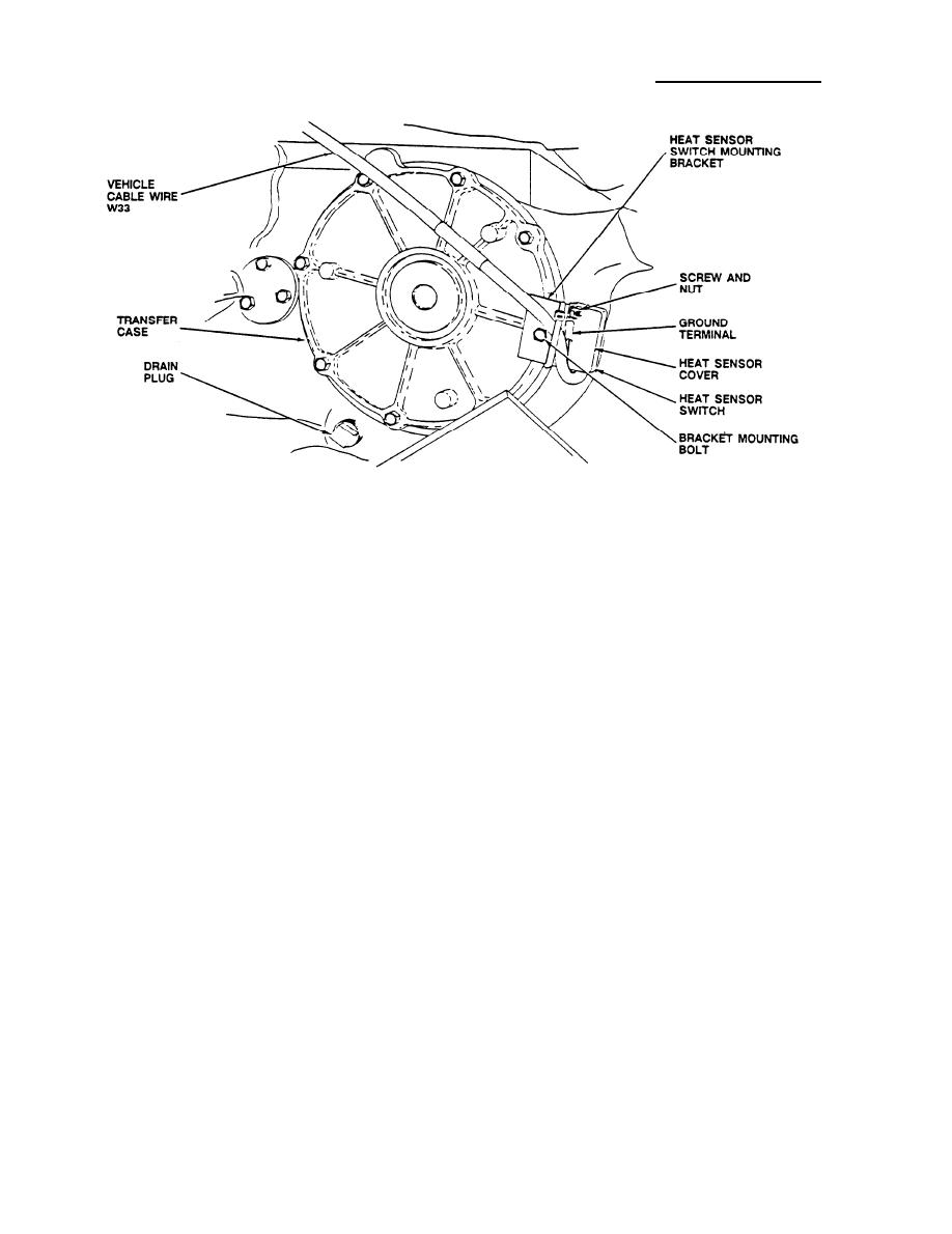
HEAT SENSOR SWITCH
Solder terminal lug (item 71, MS25036-148) on ground wire (item 72,
93.
M16878/4BCB9) to heat sensor switch terminal using 45 watt soldering iron.
Solder W-33 DRIVE TRAIN shielded wire to heat sensor switch terminal using
94.
45 watt soldering iron.
Insert grommet (item 70, MS35489-4) in heat sensor cover.
95.
Place heat sensor cover (item 35, C5122611-1) on mounting bracket. Place
96.
ground wire terminal lug (item 71, MS25036-14B) on one screw. Tighten
screws (item 66, MS24693C3), nuts (item 68, NAS671C4), and washers (item
67, NAS1640-4) using NO.1 cross tip screwdriver and 3/16" combination
wrench.
Under truck bed, route W-33 cable (item 29, C5110787-1) over curbside frame
97.
of vehicle.
Remove and retain bolt located on the right rear of the transfer case using
98,
3/8" drive ratchet handle, 6" extension, and 9/16" socket. Install the
mounting bracket on the transfer case and secure with bolt.
Check fluid level of transfer case and fill (refer to TM 9-2320-289-20) if
99.
necessary.
28


