
TM 5-3655-210-12
Malfunction
Test or Inspection
Corrective Action
5.
Engine Overheats
Step 1. Check engine for hard starting or blow back
indicating possible ignition spark out of time.
Re-time the engine (para. 4-40).
Step 2. Check for part of the air shroud removed from the
engine.
Replace missing parts (para. 4-64).
Step 3. Check for restrictions in the exhaust.
6.
Compression Low
Step 1. Inspect for a loose or broken spark plug.
Tighten spark plug. Replace a broken spark plug
by removing the coupling nut (2, fig. 4-8) and
removing plug (1).
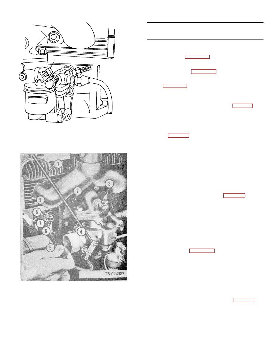
Step 2. Check the valve adjustment with an 0.012 in.
(0.0305cm) feeler gage.
Adjust the valves as follows:
a. Turn the crankshaft over by hand until the lifter
1. Screw
TS 024536
(6, fig. 4-13) that is to be adjusted is at its lowest
Figure 4-12. Idle adjusting screw.
position.
b. Insert 0.012 in. (.0305cm) feeler gage (5)
between the valve stem (8) and lifter screw (7).
Hold lifter (6) with wrench, and turn lifter
adjusting screw into or out of the lifter with
another wrench until the correct clearance is
obtained. A slight drag should be felt as the
feeler gage is moved back and forth.
7.
Power Loss In Engine
Step 1. Check for a partly closed carburetor choke.
Open choke as follows:
so that there is still enough drag to rotate the
choke control shaft.
b. Lift up on the control lever (2) until the
carburetor choke control lever (3) is in the up, or
closed position.
c. Tighten the clamp screw (1).
d When the lever (2) is released it should go back
to the intermediate position.
Step 2. Inspect for dirty air cleaner parts.
Remove, disassembly and clean or replace parts
as necessary (para. 4-26).
Step 3. Check instruments and observe sluggish engine
running (overload).
Correct operation of cylinder filling unit
8.
Pressure Vessel Pressure Too High, Alarm Bell
Does Not Ring
Step 1. Inspect tank alarm pressure switch out of adjustment
1.
Head
6.
Valve lifter
(The correct setting is 305 on the high side (knob 5) and 295
2.
Air shroud heat deflector
7.
Adjusting screw
on the low side (knob 6).
3.
Valve cover
8.
Valve stem
Adjust setting of the pressure switch as follows:
4.
Gasket
9.
Block
Adjust the tank pressure switches (4, fig. 4-15) by
turning the adjusting knobs (5 and 6) to the desired
5.
Feeler gage
setting on the scale. Set the pressure switch (8),
Figure 4-13. Tappet adjustment.
connected to the conversion heater, at 275 on the
high side and 260 on the low side.
4-15
