
TM 5-3655-210-12
e. Cleaning and Inspection. Wipe all parts with a
clean rag dampened in a solvent. Inspect contact points
for burning or pitting. Replace damaged parts, except
lightly pitted points may be filed to a smooth mating
surface.
f. Breaker Point and Condenser Installation.
Reverse the removal procedures in d. above.
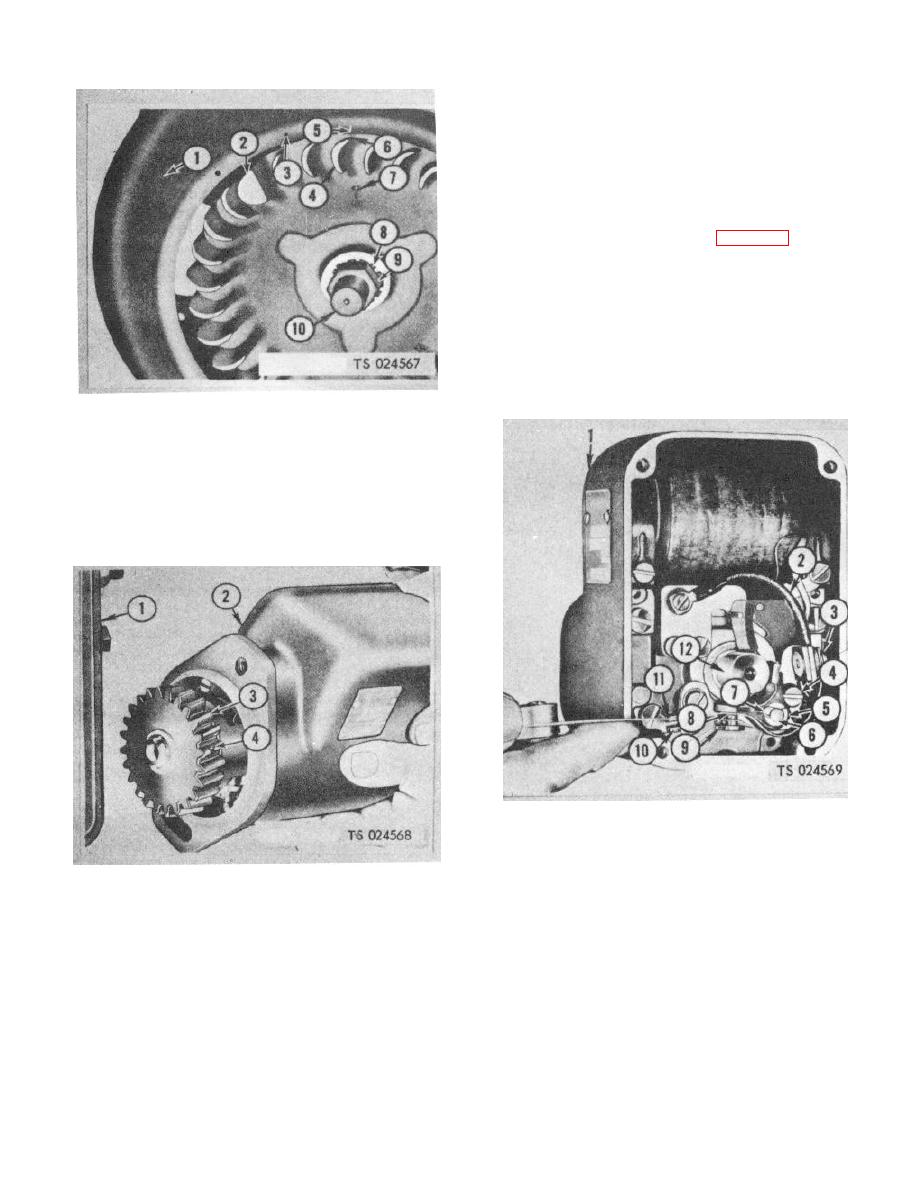
g. Breaker Point Gap Adjustment.
(1) Loosen the screws (4, fig. 4-43).
(2) Turn the rotor (12) so the points are fully
open.
(3) Insert a 0. 015 in. feeler gage (11)
between the points.
(4) Use a screwdriver in the adjusting slot
(10) to move the stationary point as needed to get
clearance producing just slight drag with gage between
points, and retighten screws (4) to hold adjustment.
1
Shroud
6
Edging vane
2
Flywheel
7
Flywheel timing mark
3
Running spark advance mark 8
Lock washer
4
Timing vane
9
Flywheel nut
5
Top dead center mark
10
Pin
Figure 4-41. Flywheel timing marks.
1.
Magneto
7.
Lock
2.
Condenser lead
8.
Breaker arm
3.
Terminal screw
9.
Fixed contact
4.
Screw
10.
Adjusting slot
1.
Timing gear cover
5.
Washer
11.
Feeler gage
2.
Magneto
6.
Pivot pin
12.
Rotor
3.
Magneto drive gear
4.
Magneto drive gear timing mark
Figure 4-43. Breaker point, removal and adjustment
Figure 4-42. Magneto gear timing marks.
4-50
