
TM 5-3655-210-12
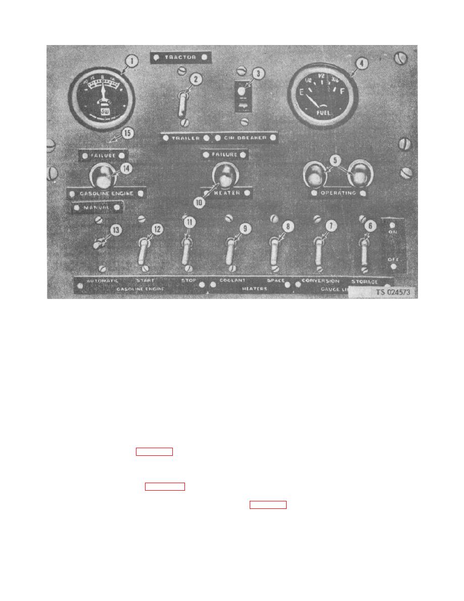
1.
9.
Conversion heater control switch
2.
Electrical control switch (tractor or trailer)
10.
Conversion heater failure light
3.
Circuit breaker
11.
Gasoline engine manual stop switch
4.
Fuel indicator gage
12.
Gasoline engine manual starter switch
5.
Gage lines operating lights
13.
Gasoline engine control switch for automatic or manual
6.
Storage vessel gage line switch
.
control
7.
Conversion vessel gage line switch
14.
Gasoline engine failure light
8.
Compartment heater control switch
15.
Engine control panel
Figure 4-47. Engine Control Panel
(3) Raise the generator and slip off the
(3) Lift the brush arm with a stiff wire and
generator drive belt (1).
remove the brush.
(4) Remove the two nuts (29), lock washers
(4) Reverse steps (1) to (3) to install brushes.
c. Generator Installation. Reverse the removal
(30), and cap screws (28) securing the generator (31) to
the frame (27). Lift out the generator.
procedure to install the generator, and tighten drive belt
(5) Remove the nut (3, fig. 4-52), lock washer
to 1-% in. (3. 81 cm) deflection at midspan.
(4) and cap screw (6) securing the adjusting bracket (9)
4-46. Pressure Switches
to the frame, releasing the strap.
b. Brush Replacement.
a. Refrigeration Compressor Pressure Switch
(1) Loosen the screw (1, fig. 4-52) securing
Adjustment. The compressor pressure switches are set
the strap (2) on the generator (5) and slide the strap
with the adjusting screws on top of the switches (1 and
from the generator.
2, fig. 4-53). Set the suction pressure switch (2) to open
(2) Remove the screw (13) securing the
at zero psi to shut off the engine or electric motor. The
brush (-12) to the brush holder' (15).
low pressure suction switches reset to
4-54
