
TM 5-3655-210-12
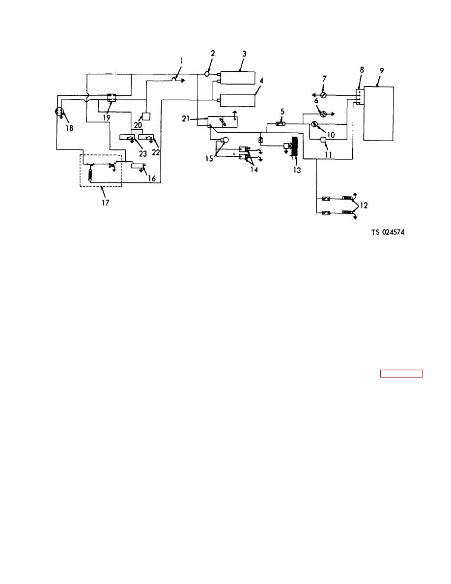
1. Gasoline engine start and stop switches
13.
Space heater
2. Ammeter
14.
Pressure alarm switch
3. Voltage regulator
15.
Alarm bell
4. Generator
16.
Starting motor
5. Heater switch
17.
Automatic engine control
6. Coolant circulating pump
18.
Pressure control switch
7. Warning light
19.
Automatic-manual engine control switch
8. Heater control plug
20.
Magneto
9. Heater
21.
Batteries
10. Tank pressure control switch
22.
Low pressure control switch
11. Limit switch
23.
High pressure control switch
12. Heating element
Figure 4-48. DC control wiring schematic
allow operations to resume when the suction pressure
(2) Remove the two nuts (3, fig. 4-55)
rises to 12 psi (. 8436 kg per sq. cm). Set the discharge
securing the wires to the fuel gage (2) or ammeter (8).
switches (high pressure) (1) to open at 240 psi (16. 872
Remove the wires from the ammeter.
kg per sq. cm) to stop the electric motor or gasoline
(3) Remove the two nuts (3) securing the
engine. The high pressure switches close to resume
clamp (7) and the unit to the control panel (19) and
operation when the pressure drops to 210 psi (14. 763
remove the clamp (7) and ammeter (8).
b. Installation. Reverse removal procedure.
kg per sq. cm). Adjust the switches to the correct
settings as indicated on the dial by using a screw driver
4-48. Automatic Starter Control
on the adjusting screw.
b. Tank Pressure Switch Adjustment. Adjust the
a. Removal.
tank pressure switches (4) by turning the adjusting
(1) Refer to the wiring diagram (fig. 4-56) and
knobs (5 and 6) to the desired setting on the scale. The
tag the wire leads connected to the starter control (9,
correct setting is 305 on the high side (knob 5) and 295
fig. 4-55).
on the low side (knob 6). The pressure switch (8),
(2) Remove the nuts securing the leads to the
connected to the conversion heater, is set at 275 on the
control terminals and remove the leads.
high side and 260 on the low side.
(3) Remove the two nuts (21) and lock
washers (22) securing the control and shock mounts
4-47. Ammeter and Fuel Gage
(20) to the mounting bracket (18) and lift out the control
a. Removal.
and mounts.
(1) Disconnect battery ground lead (2, fig. 4-
54).
4-55
