
TM 5-3655-210-12
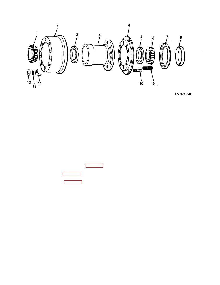
1.
Bearing cone
6.
Bearing cone
10.
Shoulder bolt
2.
Brake drum
7.
Seal
11.
Clamp,
3.
Bearing cup
8.
Wiper
12.
Lockwasher
4.
Hub
9.
Shoulder bolt
13.
Nut
5.
Adapter flange
Figure 4-71. Hub and drum assembly, exploded view.
e. Installation
(6) Position the outer bearing cone (6) on the
axle.
(1) Make sure all the old grease has been
(7) Install the inner retaining nut (7) and
removed.
tighten while turning the wheel until the bearing just
(2) Pack the bearings with lubricants; kneading
seats. Back off the nut one-third turn so that the wheel
the lubricant between the inner race and the cage by
and bearings turn freely.
hand. Coat the inside of the hub and the axle with
(8) Position the retaining ring (8) on the axle
grease to prevent rusting.
(10) and the dowel on the nut(7), and secure with the
(3) Position the rear bearing cone (6, fig. 4-69)
outer nut (9).
and the grease seal in the hub.
(9) Position the gasket (11) and hub cap (12)
(4) Slide the wiper (8, fig. 4-71) into position
on the axle and secure with the six lockwashers (13) and
on the axle.
capscrews (14).
(5) Position the hub (5, fig. 4-69) on the axle,
being careful not to damage the axle threads.
Section XVI. BRAKE SYSTEM
4-69. Description (See Fig, 4-72)
apply the brakes. The system includes connections at
a. General.
the front so the air brake system can be connected to
Air brake equipment on trailers
and operated by the air brake system of the truck or
operates the trailer brakes through compressed air in
tractor towing the trailer. Connections are provided also
conjunction with the air brake system on the truck or
at the rear of the trailer to permit connecting to a second
tractor towing the trailer. As shown in figure 4-72, trailer
trailer. Following are the devices composing the trailer
air brake system consists of the air devices necessary to
air brake system with a brief description of the function
direct and control the flow of the compressed air and
of each device.
those necessary to transform the energy of compressed
air into the mechanical force and motion necessary to
4-78
