TM 5-3655-210-12
d. Leakage Test.
(1) With system pressure up and actuators in
the released position, check drain slot and around push
rod boot with soap solution to detect possible leakage by
the locking piston grommet.
(2) Make and hold a service brake application,
and again check the actuator drain slot for diaphragm
leakage. Continue to hold the service application and
coat around the clamping ring with soap solution to
detect seal leakage. Should leakage be detected at the
clamping ring, tighten the clamping ring nuts evenly but
only enough to stop leakage.
4-75. Trailer Release Valve Replacement
a. Refer to figure 4-72 and disconnect, cap and tag
the lines to the trailer release valve.
b. Unscrew the valve and pipe nipple from the
relay-emergency valve.
c. Reverse steps a. and b. above to install valve.
4-76. Check Valve Replacement
a. Refer to figure 4-72. Disconnect, tag and cap
lines and fittings to check valve.
b. Unscrew and remove check valve from relay
emergency valve.
c. Reverse steps a. and b. above to install.
4-77. Relay Emergency Valve
a. Removal
(1) Block trailer wheels and drain air from
reservoir.
(2) Remove trailer release valve.
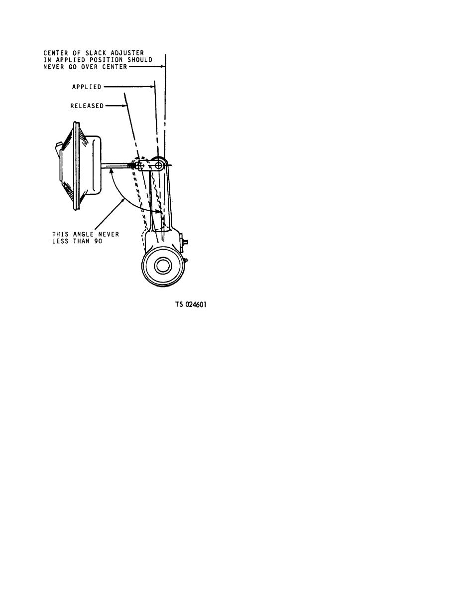
Figure 4-74. Slack adjuster, correct travel
(a) Refer to figure 4-72 and disconnect,
cap and tag the lines to the trailer release valve.
(3) Connect air lines to actuators. Take care
(b) Unscrew the valve and pipe nipple
that the correct lines are installed in correct port.
from the relay-emergency valve.
(4) Adjust brakes to correct shoe to drum
(c) Reverse steps (a) and (b) above to
clearance as follows: Refer to figure 4-73 and adjust
install valve.
each slack adjuster so the wheel brake just drags
(3) Refer to figure 4-72. Disconnect, cap and
slightly, and the angle between the push rod and slack
tag lines to valve.
adjuster arm is greater than 90 when brakes are
(4) Remove mounting bolts and take valve
applied, as shown in figure 4-74.
from reservoir.
c. Operating Test.
b. Installation. Reverse procedure in a. above
(1) With actuator in the released position,
and test as given below.
make several service brake applications and note that
c. Operating and Leakage Test. Check tractor
actuator applies and releases properly.
dash air gage against' a test gage known to be accurate
(2) Disconnect trailer emergency line or throw
prior to performing these tests. 'Connect tractor air lines
trailer into emergency by use of tractor protection valve
to the trailer on which valve is to be tested. Block
and observe that the actuator applies. Drain trailer
wheels or otherwise hold both vehicles by a means other
reservoir and observe that actuator remains applied.
than air brakes during these tests.
(3) Close trailer reservoir drain and fully
(1) Start these tests with no air pressure in
charge trailer air supply. Make and hold a heavy
tractor or trailer air brake system. During the initial
service application (about 5 seconds). Actuator should
charge of the tractor-trailer air brake system, note that
release as service application is released.
the trailer brakes are applied as the trailer emergency
4-82


