
TM 9-2510-247-13&P
0027 00
UNIT TROUBLESHOOTING - Continued
MALFUNCTION
TEST OR INSPECTION
CORRECTIVE ACTION
ELECTRICAL SYSTEM - Continued
3. VOLTMETER DOES NOT WORK - Continued
Step 3.
Are there any broken or frayed wires?
If no, go to step 4.
If yes, repair or replace wires as necessary (WP 0051).
Step 4.
Is voltage found at plus (+) side of voltmeter?
If no, ensure connection is clean and there is a good connection on (+) feed wire
If yes, replace voltmeter.
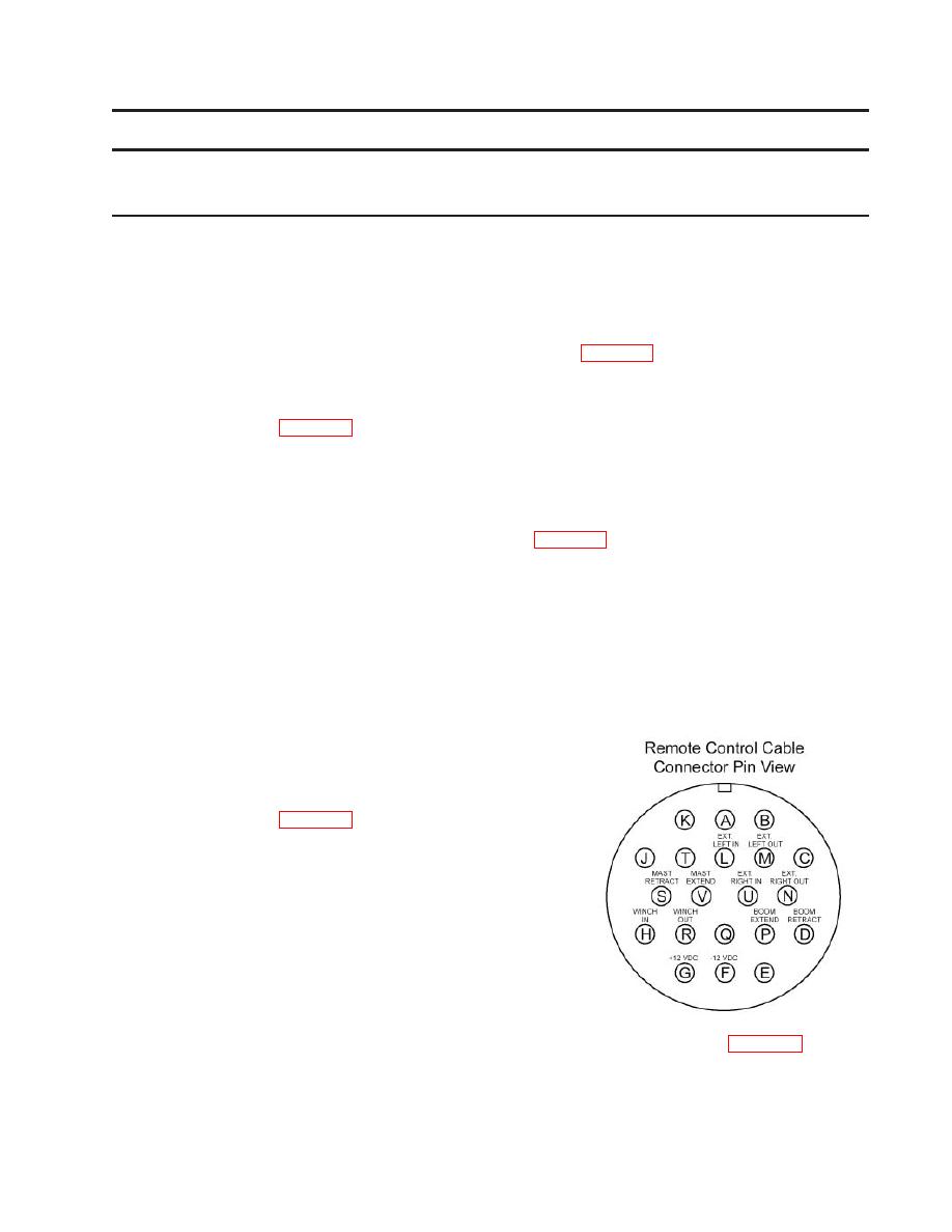
4. REMOTE CONTROL DOES NOT OPERATE
Step 1.
Is ON switch on remote in on position?
If no, place ON switch in on position (WP 0007, step 3).
If yes, go to step 2.
Step 2.
Is there minimum12VDC on batteries?
If no, go to step 3.
If yes, go to step 4.
Step 3.
Is NATO slave cable connected?
If no, install NATO cable in receptacle on prime mover and receptacle on 12/24
volt junction box.
If yes, go to step 4.
Step 4.
Is voltage coming into remote control?
If no, ensure connection is clean and
there is a good connection on (+) feed wire
If yes, go to step 5.
Step 5.
Is voltage coming out of remote control?
If no, replace remote control.
If yes, test solenoids on control valve and replace as necessasry (WP 0045).
0027 00-3
