TB 5-2520-551-24
TACHOMETER
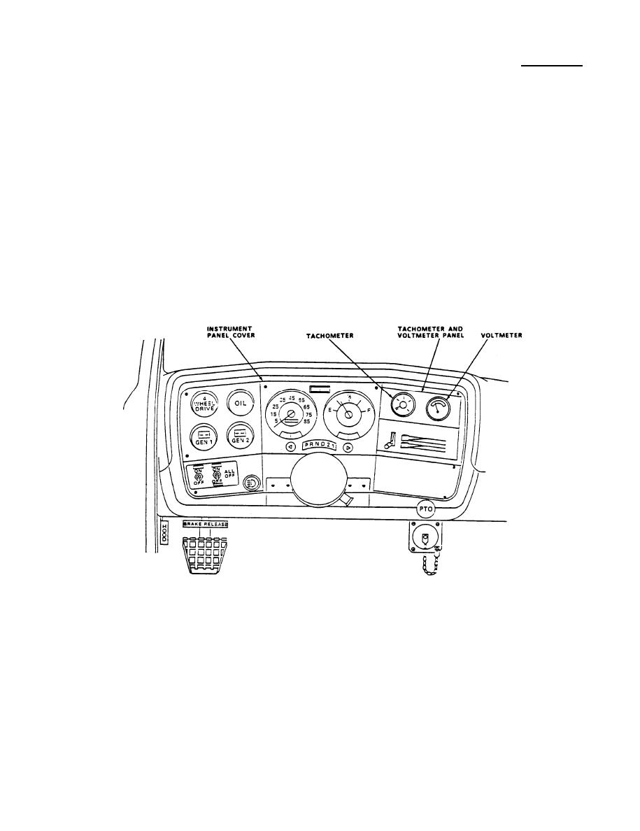
Using electric drill and 1/8" bit, drill out two rivets securing gauge
38.
panel to instrument panel.
39.
Behind instrument panel cover, using 11/32" wrench, remove and retain two
nuts securing wires to voltmeter terminals. Tag and remove wires. Remove
voltmeter lamp and housing from voltmeter.
40.
Using 3/8" combination wrench, remove and retain two nuts securing
voltmeter bracket to mounting studs. Remove and retain voltmeter bracket.
41.
Install voltmeter into right side of new gauge panel (item 28, C5110698-1).
Secure voltmeter bracket onto mounting studs with two nuts. Using a 3/8"
combination wrench, tighten nuts.
42.
Install tachometer (item 61, C51107O8-1) into left side new gauge panel
(item 28, C5110698-1). Secure tachometer bracket to panel with two nuts.
Using a 3/8" combination wrench, tighten nuts.
43.
Splice W-67 cable to tachometer wires with splices (item 88, M7928/5-3 and
item 89, M7928/5-4). Using crimping pliers, crimp splices. Reference
figure 1 at back of this bulletin.
Reconnect wires to voltmeter terminals. Secure wires with two nuts. Using
44.
11/32" combination wrench, tighten nuts. Reinstall lamp into voltmeter.
45.
Install and tighten two screws (item 65, MS51957-29) and washers (item 87,
AN960C6) securing gauge panel (item 28, C5110698-1) to instrument panel
using NO.1 cross tip screwdriver.
15


