
TB 9-2350-368-25
SECTION VI. INSTRUMENT PANEL
INSTRUMENT PANEL. The instrument panel contains the following gages, switches, and
2-6.
indicators: water temp, engine low oil pressure, trans clogged filter, trans high temp, trans low pressure,
master power, fuel, battery voltage, fuel pump, glow plug, starter, and preheater. STE-ICE is also contained
within the instrument panel with external connectors. The tachometer MS35916-2 (6680-00-825-2076) may
or may not be in the instrument panel. It was found that the tachometer, when hand-held and attached
directly to the engine, works better for moving around the engine and making adjustments.
a. Instrument Panel/Box
Bill Of Materials
Item
Nomenclature
Part Number
NSN
Qty
1/8" Aluminum Plate
1
15 by 12 inches (38.1 by 30.5 cm)
2
2
4 by 12 inches (10.2 by 30.5 cm)
2
3
4 by 15 inches (10.2 by 38.1 cm)
2
4
2 by 2 inches (5.1 by 5.1 cm)
2
Hardware
5
Black Spring Steel U-Nut
4
6
Weldnut
12296904-32
4
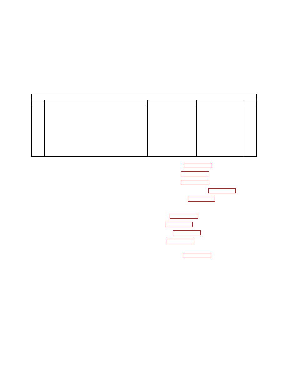
1. Cut two 1/8-inch aluminum plates, 15 inches by 12 inches (1). See Figure 2-26.
2. Cut two 1/8-inch aluminum plates, 4 inches by 12 inches (2). See Figure 2-26.
3. Cut two 1/8-inch aluminum plates, 4 inches by 15 inches (3). See Figure 2-26.
4. Measure 2, 3, 2, 3, and 2 inches across the 12-inch side of front panel (1). See Figure 2-26.
5. Measure 2, 3, and 3 inches down 15-inch side of front panel (1). See Figure 2-26.
6. Scribe four lines as measured in step 4 above and three lines as measured in step 5 above.
7. Drill three 2.108-inch diameter holes in front panel (1). See Figure 2-26.
8. Drill six 0.656-inch diameter holes in front panel (1). See Figure 2-26.
9. Drill twelve 0.177-inch diameter holes in front panel (1). See Figure 2-26.
10. Drill two 0.438-inch diameter holes in front panel (1). See Figure 2-26.
11. Weld four weldnuts (6) to inside of front panel (1). Use STE/ICE circuit card to layout weldnut pattern or
space them 2-1/2 inches by 4-1/2 inches--leave room for card. See Figure 2-26.
12. Measure 1, 3/4, 3/4, and 3/4 inch from top of side panel (3) and scribe four lines.
13. Measure 1 inch from side of back side panel (3) and scribe a line.
14. Drill four 0.468-inch holes for circuit breakers where scribe lines intersect in side panel (3).
