TM 9--2520--215--34
BRAKE AIR VALVE ASSEMBLY AND RELATED LINKAGE REPAIR –
CONTINUED
0037 00
ASSEMBLY – Continued
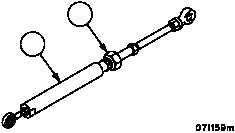
4. Install and fasten linkage rod plunger stop (15) into sleeve (16).
15
16
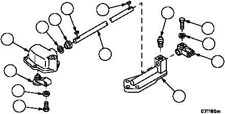
NOTE
Make certain key enters slot in brake air--valve.
5. Install new oil seal (11), retainer (12), and key (14) on brake air--valve linkage shaft (4). Position brake air--valve
assembly (10) in the brake air--valve body (13). Install the linkage shaft with new oil seal (11), retainer (12), and
key (14) through the brake air--valve body (13) and into the brake air--valve assembly (10).
6. Install cap screw (8) and lockwasher (9) in the brake air--valve assembly (10). Torque screw to 26 to 32 ft--lb.
7. Using a hammer and soft drift, seat retainer (12) and oil seal (11) in brake air--valve body (13).
8. Install lubrication fitting (7) in brake air--valve linkage bracket (6). Install key (5) on brake air--valve linkage shaft
(4) and install brake air valve linkage lever (3) on shaft (4).
9. Install cap screw (1) and lockwasher (2) on brake air--valve linkage lever (3). Torque screw to 26 to 32 ft--lb.
5
7
2
1
3
10
9
8
6
4
13
12
11
14
NOTE
FOLLOW--ON MAINTENANCE:
Brake air valve assembly removed
(WP 0036 00)
END OF TASK
0037 00--5/6 blank