TM 5-3655-210-12
TS 024498
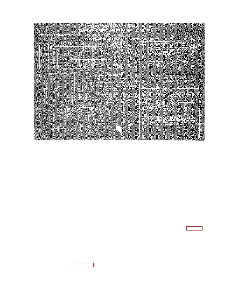
Figure 2-20. Filling both pressure vessels with liquid carbon dioxide.
f. Disengage the clutch to the transfer pump.
(stored in the storage compartment) to the liquid fill line
and vapor equalizing line at the rear of the trailer, and to
Close the liquid fill and vapor equalizing line valves on
the liquid supply unit.
the liquid supply unit.
d. Close valves 1, 3, 5, 8, 10, 27, and 28 (fig. 2-
g. Close valves 1 and 7. Open valves 27 and 28
21). Open valves 2 and 7. Open the liquid fill and
to bleed off the carbon dioxide trapped in the transfer
vapor equalizing line valves on the liquid supply unit.
hoses, and then disconnect the transfer hoses. Open
e. Open valves 1 and 10. When liquid appears at
valve 7 slightly to check for overfilling. If no liquid
carbon dioxide appears, close the valves. If the liquid
valve 10, close the valve and engage the transfer pump
carbon dioxide appears through the valve, leave the
clutch.
Continue to pump liquid into the storage
valve open until the discharge changes to a clean or
pressure vessel until it is full. To determine when the
blue fog discharge.
pressure vessel is full, check as follows:
h. Set the unit for automatic operation and engage
(1) Determining Liquid Level While Pumping.
(a) Liquid Level Gage. The unit is equipped so
only the refrigeration clutch. Position the valves in the
normal positions as indicated in Figure 2-13.
that the liquid level gages (2 and 4, fig. 2-4) indicate the
contents of the pressure vessels (in tenths of capacity)
2-10.
Filling The Storage Pressure Vessel With
even during pumping. Thus the contents can be
Liquid Carbon Dioxide (Both Pressure
determined by reading the gages and allowing for slight
Vessels Empty)
time lag.
(b) Liquid in Vapor Equalizing Line. When
a. Set the driving unit for manual operation, and
filling the pressure vessels, it is usually desirable to fill
disengage all clutches.
b. Set the valves as indicated in Figure 2-21 and
them completely. The normal course of the carbon
dioxide during filling is for liquid to enter at the bottom of
start the driving unit. Refer to Table 2-1 for valve
the vessels while carbon dioxide vapor flows out at the
identification.
c. Connect the liquid and vapor transfer hoses
top of the vessels, returning to the tank from which the
liquid is being pumped. When the liquid level in the
pressure vessel rises until it
2-19


