
TM 5-3655-210-12
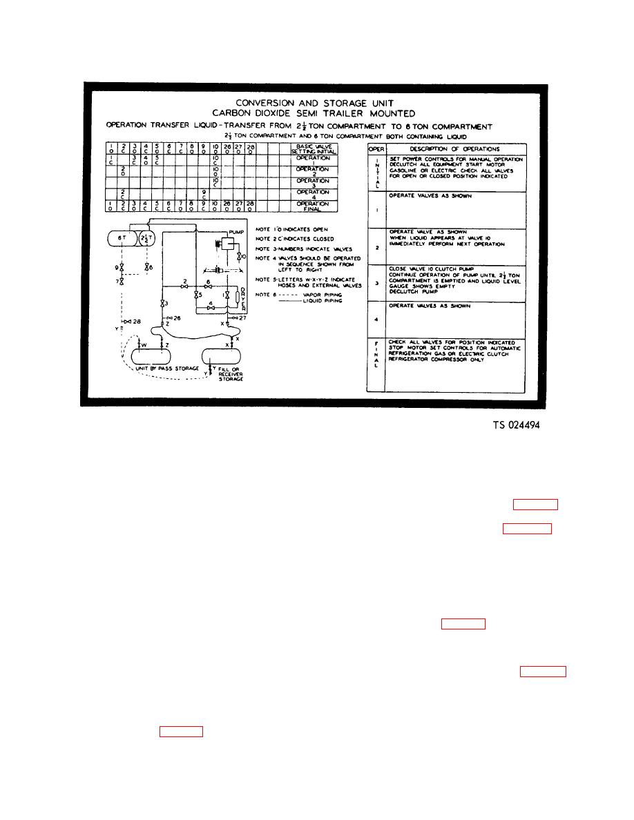
Figure 2-16. Transfer of liquid from the conversion pressure
vessel to the storage pressure vessel.
values are indicated, close valves 8 and 9, and then
(1) Set the driving unit for manual operation
open valve 7. This will allow liquid carbon dioxide to
and disengage all clutches (1, 2, and 3, fig. 2-3).
cover the heater coils at the bottom of the conversion
(2) Set the valves as indicated in Figure 2-16
pressure vessel, and prevent the heater thermostat
and start the driving unit. Refer to Table 2-1 for valve
switch from opening as often as in a normal conversion
identification.
operation.
(3) Close valves 1, 3, 5, and 10 (fig. 2-16).
f. The conversion heater will cycle on and off
Open valve 4. Open valves 2 and 10. When liquid
carbon dioxide appears at valve 10, close the valve and
during the initial stages of conversion. This will occur
engage the clutch to the transfer pump.
since the heater fluid circulating through the coil is not
(4) Continue to operate the transfer pump until
sufficiently cooled by the carbon dioxide, and causes the
the conversion pressure vessel is empty, as indicated by
heater thermostat switch to open and close. The heater
the liquid level gage (6, fig. 2-4).
will continue to operate until the temperature of the
(5) Disengage the transfer pump clutch and
heating fluid, returning to the heater, reaches 73.9C.
close valves 2 and 9.
(165F.). The heater will remain off until the fluid
(6) Set the unit for automatic operation, and
temperature reduces to 65.6C. (150F.). The conversion
engage only the refrigeration clutch (3, fig. 2-3). With
cycle will continue until the pressure in the conversion
all the liquid contained in the storage pressure vessel,
pressure vessel reaches 275 psi (19.3325 kg per sq cm).
the valve should be in the normal position as indicated
At this pressure, the tank pressure control switch will
in Figure 2-13. If the liquid level and pressure is to be
open the circuit, to stop the heater.
g. After conversion is complete, turn off the
equalized in both tanks, close valve 7 and then open
valves 5, 8 and 9. This will provide refrigeration for the
conversion heater switch (9, fig. 2-2) and if the liquid is
contents of both pressure vessels.
to be transferred to the storage pressure vessel, transfer
as follows:
2-15
