
TM 5-3655-210-12
refrigeration for the contents of both pressure vessels,
and to equalize the liquid levels and pressures.
2-7. Reduced Conversion Cycle
a. This operation can be performed only when
liquid carbon dioxide is present in the storage pressure
vessel. Perform the following steps when converting
solid carbon dioxide into the conversion pressure
vessel. The refrigeration controls should be set for
automatic operation as follows: Make certain the motor
starting switch and the reversing switch are in the OFF
position; and the power line is connected to the trailer
208 VAC power receptacle (1, fig. 2-11). Disengage
the three countershaft clutches (1, 2, and 3, fig. 2-3).
Turn the motor' starting switch (fig. 2-9) to the HAND
position. Turn the reversing switch to one of the ON
positions only long enough to observe the rotation of the
shaft. The shaft should rotate counterclockwise when
viewed from the shaft end of the motor. If the shaft
rotates in the proper direction, turn the motor starting
switch to the AUTOMATIC position, and return the
reversing switch to the same ON position. If the shaft
rotates in the wrong direction, turn the motor starting
switch to the alternate ON position. The position of the
reversing switch must not be changed unless a power
source of different phase sequence is used. With the
above steps performed, the electric motor will start
whenever the high tank pressures close the tank
pressure switch, which controls the electric motor. The
refrigeration clutch (3, fig. 2-3) engaged.
b. Position the valves as indicated in figure 2-17.
Refer to Table 2-1 for valve identification.
c. When the pressure in the conversion pressure
vessel is 0 psi, close valve 8. Open the manway on the
conversion pressure vessel and pack the vessel with
approximately 4,000 pounds (1800 kg) of solid carbon
dioxide. Reseal the manway as follows:
(1) Install the gasket (2, fig. 2-15) on the
cover (1).
(2) Position the cover in the vessel.
(3) Position the bolts (6), clamps (5),
1.
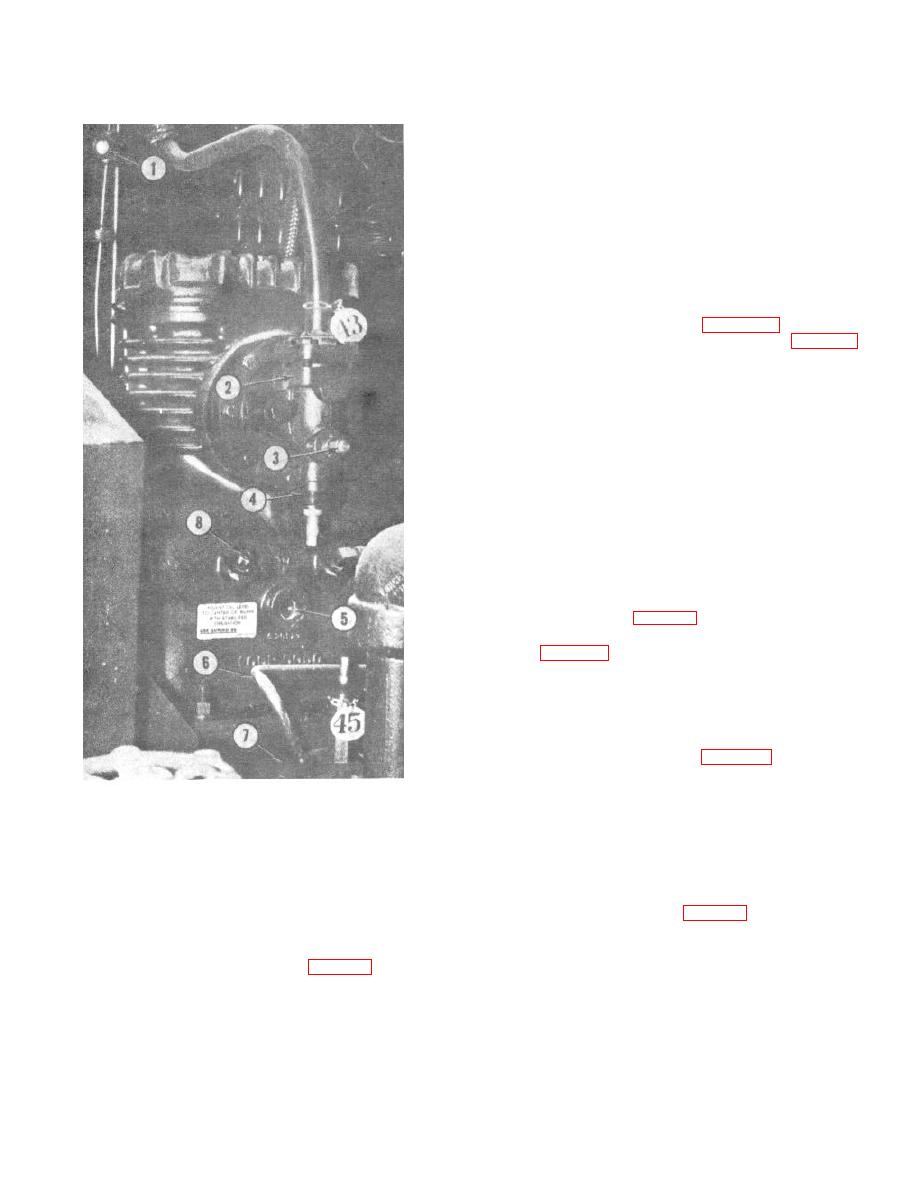
Refrigerant sight glass
5.
Oil level sight glass
flatwashers (4), and secure with the nuts (3).
2.
Suction valve
6.
Receiver tank inlet line
(4) Replace the block of insulation (2, fig. 2-
3.
Freon charging port
7.
Receiver
14).
4.
Suction valve shut-off
8.
Oil filler plug
(5) Lower the hatch (1), and secure with locks
Figure 2-12. Refrigeration compressor, installed view.
(4).
d. Turn on the switch, (9, fig. 2-2), mounted on the
(5) Disengage the transfer pump clutch and
dc control panel, to start the conversion heater.
close valves 2 and 9.
e. To reduce the conversion cycle time, close
(6) Set the unit for automatic operation, and
valve 7 (fig. 2-17) and then open valves 8 and 9. Keep
engage only the refrigeration clutch (3, fig. 2-3).
the valves in this position until the conversion pressure
With all the liquid contained in the storage pressure
vessel pressure increases to 60 psi (4.218 kg per sq
vessel, the valves should be in the normal position as
cm), or the storage pressure vessel pressure reduces to
indicated in figure 2-13.
150 psi (10.545 kg per sq cm). When either of these
(7) If liquid was contained in the storage
pressure vessel during conversion, close valve 7 (fig. 2-
13) and then open valves 5, 8 and 9 to provide
2-13
