TM 5-3655-210-12
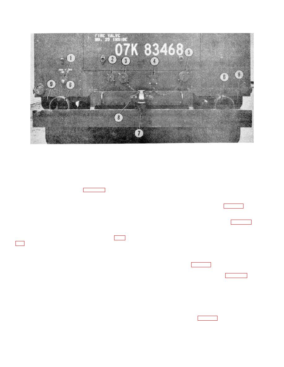
1. 208 v, ac power receptacle
4. 24 v, de receptacle
7. Pintle hook
2. Vapor equalizing line
5. Liquid fill line
8. Capscrew
3. Liquid fill line (pump by-pass)
6. Blackout stop and taillight
9. Stop and taillight, service
Figure 2-11 .
Power receptacles, installed view.
soap and water to the hatch seal. Bubbles will indicate
(1) Install the gasket (2, fig. 2-15) on the
a leak.
cover (1).
i. After conversion is completed, turn off the
(2) Position the cover in the vessel.
(3) Position the bolts (6), clamps (5),
conversion heater control switch (9, fig. 2-2) and if the
flatwashers (4), and secure with the nuts (3).
liquid is to be transferred to the storage pressure vessel,
(4) Replace the block of insulation (2, fig. 2-
transfer as follows: (1) Set the driving unit for manual
14).
operation by placing toggle switch (2, fig. 2-2) in the
(5) Lower the hatch (1), and secure with locks
trailer position. The circuit breaker (3), mounted on the
(4).
engine control panel should be ON or in the up position.
Prime the carburetor. Hold the gasoline engine START
switch (12) mounted on the engine control panel up,
until the engine starts, then release the switch. To stop
the conversion heater.
h. The conversion heater will cycle on and off
the engine hold the engine STOP switch (11) up until
the engine is completely stopped.
Disengage all
during the initial stages of conversion. This will occur
clutches (1, 2, and 3, fig. 2-3).
since the heater fluid circulating through the coil is not
(2) Set the valves as indicated in figure 2-16
sufficiently cooled by the carbon dioxide, and causes the
and start the driving unit. Refer to Table 2-1 for valve
heater thermostat switch to open and close. The heater
identification.
will continue to operate until the temperature of the
(3) Close valves 1, 3, 5 and 10 (fig. 2-16).
heating fluid, returning to the heater, reaches 73.9C.
Open valve 4. Open valves 2 and 10. When liquid
(165F.). The heater will remain off until the fluid
carbon dioxide appears at valve 10, close the valve and
temperature reduces to 65.6C. (150F.). The conversion
engage the clutch to the transfer pump.
cycle will continue until the pressure in the conversion
(4) Continue to operate the transfer pump until
pressure vessel reaches 275 psi (19.3325 kg per sq cm).
the conversion pressure vessel is empty, as indicated by
At this pressure, the tank pressure control switch will
the liquid level gage (2, fig. 2-4).
open the circuit, to stop the heater. During the use of
the conversion vessel the hatch cover should be
periodically leak tested by applying a solution of
2-12


